




Oscillateur à cristal vs oscillateur MEMS : Guide complet de sélection
Choisir entre oscillateurs à cristal et MEMS détermine si votre circuit de synchronisation résiste à des chocs de 3 000 g dans les environnements automobiles, maintient une stabilité de ±10 ppm sur les plages de température industrielles, ou s’intègre dans des empreintes de circuit imprimé de 2 mm² pour les conceptions portables. Les ingénieurs optent fréquemment pour les cristaux de quartz sans évaluer des alternatives MEMS qui offrent une résistance aux chocs supérieure de 200× et des emballages 50 % plus petits à un coût comparable. Ce guide compare les principes de fonctionnement, la stabilité des fréquences, la performance environnementale et l’adéquation des applications avec les cadres de sélection pour les systèmes industriels, automobiles et IoT.
Les catégories de produits de Hitop Tech Limited incluent des fournisseurs de composants de chronométrage vérifiés avec une traçabilité complète et une gestion compétitive des délais de réalisation pour la production en volume.
Table des matières
- [Fondamentaux de la technologie des oscillateurs] (#oscillator-fondamentaux)
- [Architecture et performance des oscillateurs à cristal] (#crystal-architecture)
- [Technologie et avantages des oscillateurs MEMS] (technologie #mems)
- Comparaison de stabilité de fréquence à travers la température
- [Chocs, vibrations et résilience environnementale] (#environmental-résilience)
- [Considérations sur le coût, la taille et la chaîne d’approvisionnement] (#cost-considérations d’approvisionnement)
- FAQ
- Conclusion
Fondamentaux de la technologie des oscillateurs
Les circuits de chronométrage nécessitent des références de fréquence stables pour les horloges du microcontrôleur, les interfaces de communication et les systèmes de mesure de précision. Les oscillateurs à cristal utilisent des résonateurs de quartz piézoélectrique atteignant une stabilité de ± à 10-50 ppm. Les oscillateurs MEMS utilisent des résonateurs en silicium avec des PLL intégrés, atteignant une stabilité de ±20 à 100 ppm dans des boîtiers 70 % plus petits que les équivalents en quartz.
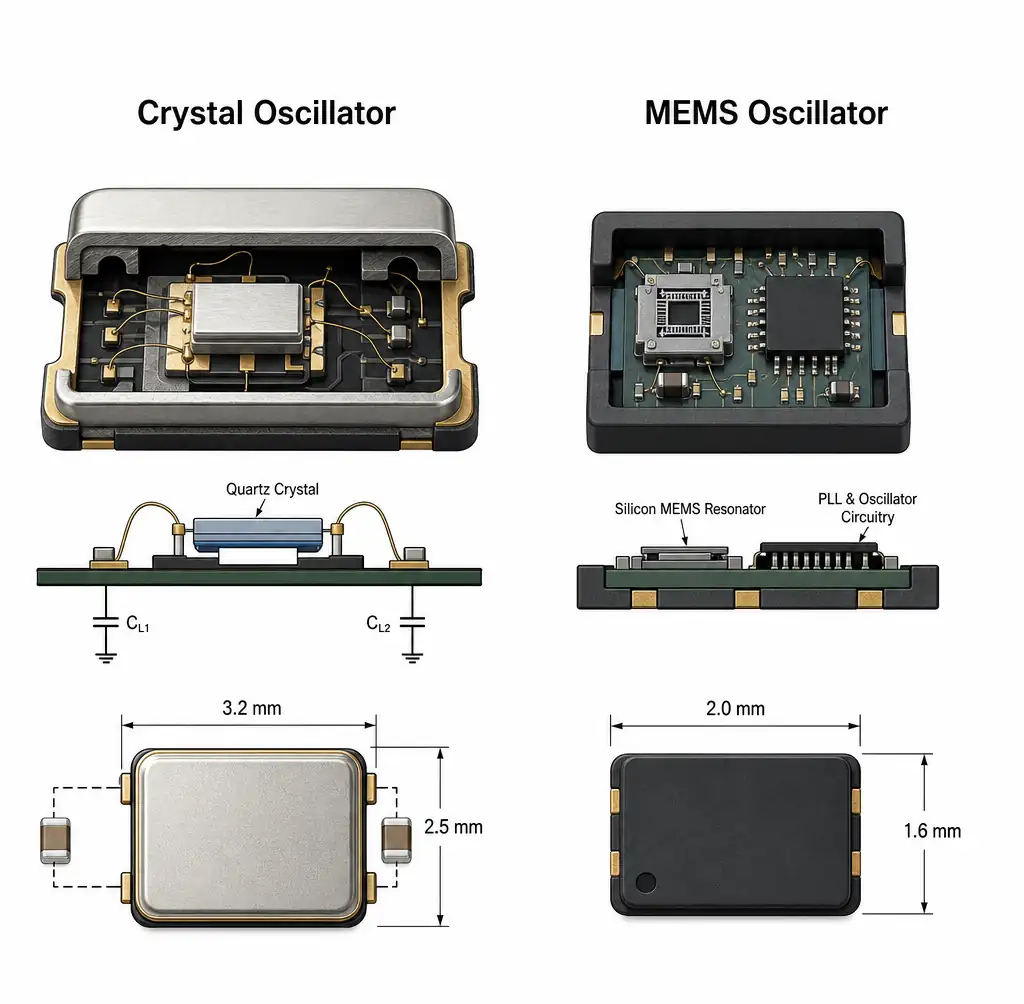 Comparaison côte à côte entre oscillateur cristal et oscillateur MEMS montrant la structure interne
Le compromis en ingénierie repose sur cinq paramètres : la stabilité en fréquence par rapport à la température, la résistance aux chocs et vibrations, le temps de démarrage, la consommation d’énergie et la taille du boîtier. Les oscillateurs à cristal excellent dans la précision absolue des fréquences avec des taux de vieillissement inférieurs à 1 ppm/an. Les oscillateurs MEMS offrent une robustesse mécanique supérieure avec une survie de choc de 50 000 g et un démarrage de 2 à 5 ms contre 10 à 20 ms pour les cristaux.
Les applications exigeant une stabilité de ±1 ppm sur 10 ans — instrumentation de précision, infrastructures télécoms, récepteurs GPS — nécessitent des oscillateurs à cristal compensés par la température (TCXO) ou des variantes contrôlées par four (OCXO). Les applications privilégiant la fiabilité mécanique, la taille compacte ou le réveil rapide après le sommeil — capteurs automobiles, IoT industriel, objets portables grand public — bénéficient d’oscillateurs MEMS échangeant 2 à 3 × spécifications de stabilité assouplies contre des avantages opérationnels.
Architecture et performance des oscillateurs à cristal
Les oscillateurs à cristal exploitent l’effet piézoélectrique du quartz — l’application de tension déforme le réseau cristallin, et la contrainte mécanique génère de la tension. Un blank de quartz découpé AT résonne à sa fréquence fondamentale avec des facteurs de qualité (Q) atteignant 50 000 à 100 000, fournissant une résonance aiguë et un faible bruit de phase.
 Résonateur à quartz découpé AT montrant la structure piézoélectrique et le placement des électrodes
Les oscillateurs à cristal standard (XO) offrent une stabilité de ±50 à 100 ppm de -40°C à +85°C avec un temps de démarrage de 10-20 ms et un courant de fonctionnement de 5 à 20 μA. Les variantes à compensation de température (TCXO) ajoutent une compensation interne réduisant la dérive à ±0,5-5 ppm sur la température à 2-3 × de coût premium. Les oscillateurs contrôlés par tension (VCXO) permettent une plage de réglage de ± 50 à 200 ppm pour les applications de synthèse de fréquence et de récupération d’horloge.
Le vieillissement cristallin suit des courbes prévisibles — la fréquence initiale varie de 1 à 5 ppm la première année, puis se stabilise à 0,5 à 1 ppm/an par la suite. Cette stabilité à long terme convient aux références de précision du temps et d’étalonnage. La contrainte est la fragilité mécanique : les cristaux de quartz se fissurent sous des vibrations ou des chocs soutenus dépassant 100-500g, provoquant des sauts de fréquence ou une défaillance complète.
| Paramètre | XO standard | TCXO | VCXO | OCXO |
|---|---|---|---|---|
| Stabilité en fréquence (-40°C à +85°C) | ±50-100ppm | ±0,5-5 ppm | ±50ppm (non calibré) | ±0,1-1ppm |
| Temps de démarrage | 10-20ms | 10-20ms | 10-20ms | 3-5 minutes |
| Consommation d’énergie | 5-20μA | 1-5mA | 10-50μA | 0,5-2W |
| Résistance aux chocs | 100-500g | 100-500g | 100-500g | 50-100g |
| Vieillissement (par an) | 1-3ppm | 0,5-2 ppm | 1-3ppm | 0,1-1 ppm |
| Coût (relatif) | 1× | 2-4× | 1.5-2× | 20-50× |
Technologie et avantages des oscillateurs MEMS
Les oscillateurs MEMS intègrent des résonateurs en silicium avec des boucles à verrouillage de phase (PLL) et des circuits de compensation sur une seule puce. Le résonateur — un faisceau de silicium vibrant, un disque ou un résonateur acoustique en vrac — atteint des facteurs Q de 5 000 à 20 000, inférieurs au quartz mais suffisants pour le microcontrôleur et la synchronisation des communications lorsqu’ils sont combinés à la multiplication de fréquence PLL.
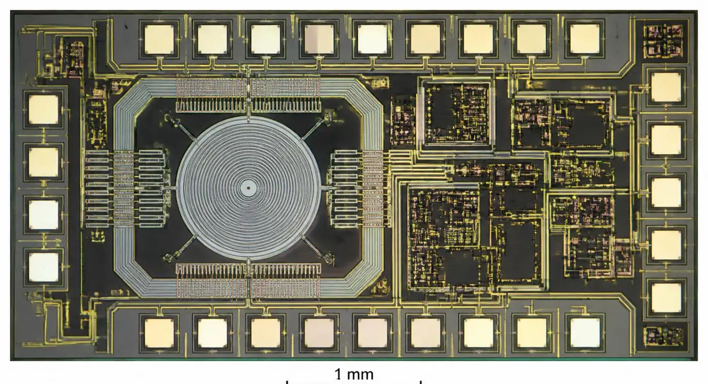 Die oscillateur MEMS en silicium montrant résonateur intégré et circuit PLL
Les propriétés mécaniques du silicium offrent une résistance aux chocs supérieure de 200 × par rapport au quartz. Les oscillateurs MEMS résistent à des chocs de 50 000g et fonctionnent à travers des vibrations soutenues de 70g avec une déviation de fréquence inférieure à 1 ppm—essentielle pour les capteurs de collision automobiles, l’automatisation industrielle et les équipements robustes portatifs. Le temps de démarrage tombe à 2-5 ms contre 10-20 ms pour les cristaux, réduisant la latence de réveil après l’endormissement dans les capteurs IoT alimentés par batterie alternant entre modes actif et mode veille.
L’intégration des paquets privilégie la production composée par rapport à la production en volume. Les oscillateurs MEMS dans des boîtiers de 2,0×1,6 mm ou 1,5×0,8 mm éliminent le cristal externe et les deux condensateurs de charge nécessaires aux entrées du microcontrôleur en cristal, économisant ainsi une surface de circuit imprimé de 6 à 10 mm² et trois opérations de positionnement. Pour les appareils portables, les objets auditifs et les nœuds capteurs denses, cette intégration permet des conceptions impossibles avec des cristaux discrets.
La stabilité thermique atteint ±20-50 ppm de -40°C à +125°C sans compensation — adéquate pour les interfaces UART, I²C et SPI nécessitant une tolérance de ±1-2 %. Les applications exigeant une stabilité plus stricte utilisent des MEMS dotés en usine avec une stabilité totale de ±20 ppm, correspondant aux performances TCXO à moindre coût. Le compromis est le vieillissement : les oscillateurs MEMS se déplacent de 3 à 5 ppm la première année contre 1 à 3 ppm pour les cristaux.
Comparaison de stabilité de fréquence à travers la température
La stabilité de la fréquence détermine si une référence de synchronisation de communication maintient la synchronisation de communication, respecte les marges de synchronisation du protocole ou conserve l’étalonnage à travers les conditions environnementales. Les deux technologies atteignent la stabilité requise par l’application grâce à des mécanismes différents.
Les oscillateurs à cristaux présentent des courbes de température paraboliques — des pics de fréquence proches de 25°C avec une déviation symétrique vers les extrêmes de température. Les cristaux de coupe AT pour modes fondamentaux de 20 à 50 MHz présentent une stabilité typique de -40°C à +85°C de ±30-50 ppm sans compensation. La sélection de la capacité de charge et la capacité parasite de la disposition du circuit imprimé influencent la fréquence absolue — chaque décalage de 1pF déplace la fréquence de 5 à 15 ppm selon la résistance en série cristalline.
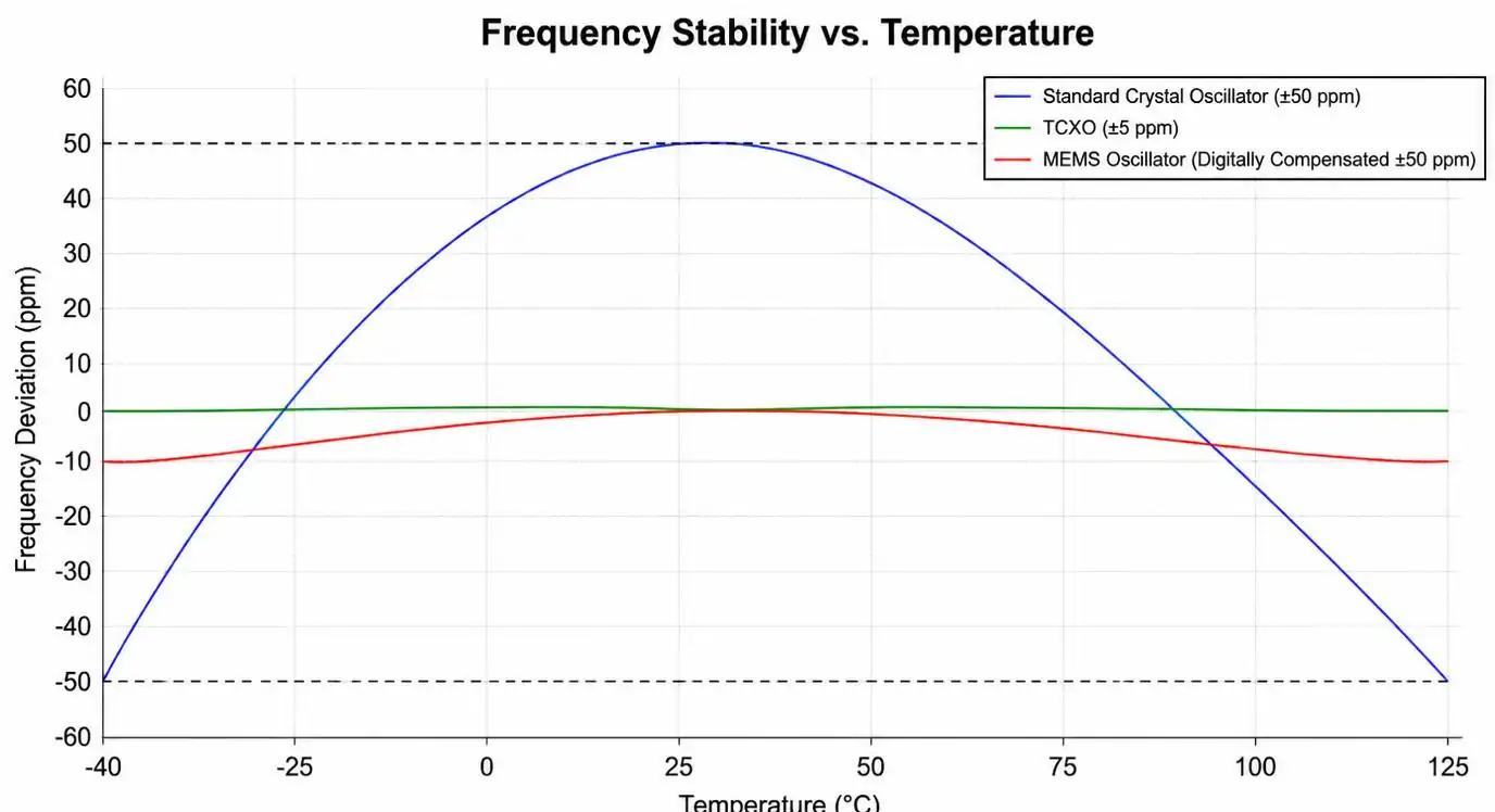 Stabilité de fréquence vs courbes de température pour les oscillateurs à cristal et MEMS
Les oscillateurs MEMS compensent les effets de température grâce à des tables de consultation intégrées et à une correction algorithmique stockée lors de la caractérisation en usine. Les résonateurs en silicium ont des coefficients de température 100 × supérieurs à ceux du quartz, mais la compensation numérique réduit l’erreur système à ±20-50 ppm sur toute la plage de température industrielle. L’avantage est l’insensibilité à la capacité des PCB — les sorties MEMS pilotent directement les niveaux logiques CMOS sans condensateurs externes, éliminant ainsi la variation de fréquence des tolérances de fabrication des PCB.
Les applications utilisant des cristaux comme sources d’horloge microcontrôleur doivent tenir compte de la précision totale du système : tolérance cristalline (±30 ppm), décalage de capacité de charge (±10 ppm), dérive de température (±50 ppm), vieillissement (±3 ppm/an) et erreur d’étalonnage initiale (±20 ppm). Le budget total d’erreur atteint ±113 ppm—suffisant pour USB 2.0 (±500 ppm), Ethernet PHY (±100 ppm) et bus CAN (±1,5 %), mais marginal pour USB 3.0 (±300 ppm) ou les capteurs en temps de vol nécessitant ±50 ppm.
| Application | Stabilité requise | Solution cristalline | Solution MEMS | Choix recommandé |
|---|---|---|---|---|
| Horloge microcontrôleur (UART, I²C, SPI) | ±1 000-5 000 ppm | XO standard (±50ppm) | MEMS standard (±50ppm) | MEMS (plus petit, robuste) |
| USB 2.0 (480Mbps) | ±500ppm | XO standard (±50ppm) | MEMS standard (±50ppm) | Soit (axé sur les coûts) |
| Ethernet PHY (10/100Mbps) | ±100ppm | XO standard (±50ppm) | MEMS standard (±50ppm) | MEMS (immunité aux chocs) |
| CAN Bus (automobile) | ±1,5 % (15 000 ppm) | XO standard (±50ppm) | MEMS standard (±50ppm) | MEMS (vibration) |
| USB 3.0 (5Gbps) | ±300ppm | TCXO (±5ppm) | MEMS de précision (±20ppm) | TCXO (spécification plus précise) |
| Échantillonnage ADC de précision | ±10-50ppm | TCXO (±1 ppm) | MEMS de précision (±20ppm) | TCXO (vieillissement à long terme) |
Choc, vibrations et résilience environnementale
Les environnements de contrainte mécanique séparent de manière décisive les oscillateurs de cristal et MEMS. Les cristaux de quartz échouent par fracture, sauts de fréquence ou perte d’activité lorsque l’énergie mécanique dépasse la limite élastique du cristal. Les résonateurs en silicium MEMS résistent à des forces qui briseraient complètement le quartz.
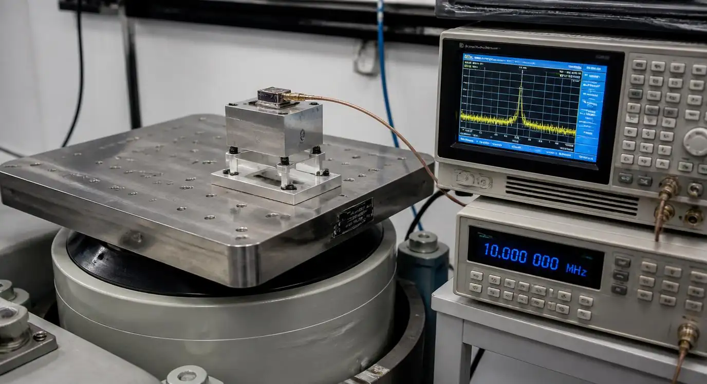 Équipement de test de chocs et de vibrations avec oscillateur en cours de test
Les modules de capteurs de collision automobiles subissent des chocs de 3 000 à 5 000g lors des tests de déploiement. Les scanners portatifs industriels subissent des chutes répétées de 1,5 m sur le béton — équivalentes à 1 500 g d’impulsions de choc. Les capteurs IoT sur les chantiers montés sur des équipements pneumatiques voient des vibrations continues de 50 à 70g. Les oscillateurs à cristal dans ces environnements nécessitent un montage de choc, des composés de potting et une isolation mécanique, ce qui ajoute coût et volume. Les oscillateurs MEMS fonctionnent à travers ces événements sans protection.
Les tests de qualification révèlent cet écart. Les tests de choc MIL-STD-883 Méthode 2002 soumettent des composants à des impulsions semi-sinusoïdales de 1 500g. Les oscillateurs à cristal spécifient généralement un maximum de 100-500g avec des limites de saut de fréquence de 10-50 ppm et aucune clause de dommage permanent à des niveaux inférieurs. Les oscillateurs MEMS spécifient une survie de choc de 50 000 g avec une déviation de fréquence de <1 ppm pendant l’événement — un avantage de performance de 100 à 200 ×.
Les interférences électromagnétiques (EMI) et le bruit de l’alimentation affectent les deux technologies, mais par des mécanismes différents. Les cristaux couplent le bruit via des circuits amplificateurs d’oscillateur, nécessitant des condensateurs de dérivation locale de 10-100 nF et des chemins de retour à la terre soigneusement. Les oscillateurs MEMS intègrent la régulation de tension intégrée à des architectures différentielles et différentielles, rejetant le bruit d’alimentation de 40 à 60 dB. Pour les conceptions automobiles et industrielles confrontées à des transitoires de charge-décharge de 40V et des limites d’émissions conduites, les oscillateurs MEMS simplifient le filtrage de l’alimentation.
Considérations sur le coût, la taille et la chaîne d’approvisionnement
Le coût total du système inclut le prix des composants, la surface des circuits imprimés, les opérations d’assemblage et la complexité de la chaîne d’approvisionnement. Les oscillateurs MEMS offrent souvent un coût total inférieur malgré une hausse de 10 à 30 % des prix des composants.
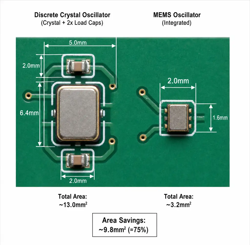 Disposition du circuit imprimé montrant la comparaison de la taille de l’empreinte entre le cristal avec condensateurs de charge et l’oscillateur MEMS intégré
Le prix des composants en volumes de 10 000 pièces montre les cristaux entre 0,15 et 0,40 $ et les MEMS entre 0,25 et 0,60 $ pour les appareils industriels standards de 16 à 48 MHz. L’écart se réduit aux hautes fréquences — les MEMS de 60 à 150 MHz coûtent entre 0,40 et 0,80 $ contre 0,30-0,70 $ pour les cristaux d’harmoniques nécessitant des circuits oscillateurs externes. Les MEMS de qualité automobile (AEC-Q100, -40°C à +125°C) coûtaient entre 0,50 et 1,20 $ contre 0,40-1,00 $ pour les cristaux plus les circuits intégrés oscillateurs discrets.
Les composés avantageux de la surface des circuits imprimés dans les conceptions denses. Une solution cristalline discrète occupe 3,2×2,5 mm (cristal) plus deux condensateurs 0402 — empreinte totale de 12 à 15 mm². Un oscillateur MEMS de 2,0×1,6 mm nécessite 3,2 mm² sans composants externes — soit une réduction de la surface de 4×. Pour les appareils portables et les capteurs miniaturisés, cela permet des conceptions autrement impossibles.
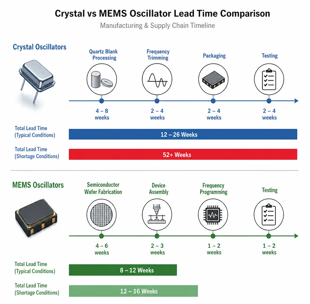 Comparaison des délais de la chaîne d’approvisionnement montrant les délais de livraison des oscillateurs cristal vs MEMS
Les délais d’exécution et la résilience de la chaîne d’approvisionnement favorisent les MEMS. La fabrication de cristaux nécessite des blanks de quartz, un recouvrement précis et une caractérisation en fréquence sur la température — les délais de livraison s’étendent de 12 à 26 semaines pour des fréquences personnalisées ou des spécifications de tolérance stricte. Les oscillateurs MEMS utilisent des fonderies de semi-conducteurs standard avec des délais de réalisation de 8 à 12 semaines et une programmation en fréquence plus large. Pendant la pénurie de composants 2020-2022, les délais de livraison des cristaux ont dépassé 52 semaines tandis que les MEMS sont restés entre 12 et 16 semaines.
Nos services de consolidation des fournisseurs aident les équipes d’achats à optimiser le timing de l’approvisionnement en composants chez les fournisseurs de cristaux et MEMS, réduisant les délais grâce au positionnement stratégique des stocks et les économies grâce à l’agrégation de volume.
| Facteur de sélection | Oscillateur à cristal | Oscillateur MEMS | Avantage |
|---|---|---|---|
| Coût des composants (10K PC) | 0,15-0,40 $ | 0,25-0,60 $ | Cristal (10-30 % de moins) |
| Empreinte du circuit imprimé | 12-15mm² (avec capuchons) | 3,2 mm² (intégré) | MEMS (4× plus petits) |
| Opérations d’assemblage | 3 placements | 1 Placement | MEMS (plus simple) |
| Délai d’exécution (fréquence standard) | 12-26 semaines | 8-12 semaines | MEMS (plus rapide) |
| Stabilité de la fréquence | ±10-50ppm | ±20-50ppm | Cristal (2× mieux) |
| Résistance aux chocs | 100-500g | 50 000g | MEMS (100× mieux) |
| Vieillissement à long terme | 1-3 ppm/an | 3-5 ppm/an | Cristal (mieux) |
FAQ
Quand devrais-je choisir les oscillateurs à cristal plutôt que les MEMS ?
Choisissez des cristaux pour des applications nécessitant une stabilité absolue de ±1 à 5 ppm sur 10+ ans — récepteurs GPS, instrumentation de précision, synchronisation télécom ou références d’étalonnage. Les cristaux offrent un vieillissement à long terme supérieur (1-3 ppm/an contre 3-5 ppm pour les MEMS) et un meilleur bruit de phase pour les applications RF. Si votre conception fonctionne dans des environnements mécaniques bénins et que la stabilité de la fréquence compte plus que la résistance aux chocs, les cristaux restent optimaux.
Les oscillateurs MEMS peuvent-ils remplacer les cristaux pour l’horloge par microcontrôleur ?
Oui, les oscillateurs MEMS répondent aux exigences de synchronisation pour la plupart des périphériques microcontrôleurs — UART (±2 %), I²C (±50 %), SPI (±2 %), USB 2.0 (±0,05 %) et bus CAN (±1,5 %). Les MEMS standards atteignent une performance cristalline d’adaptation de stabilité de ± 50 ppm. L’avantage est 4 × moins d’encombrement, 200 × meilleure résistance aux chocs et 2 × de démarrage plus rapide — essentiels pour le passage entre modes veille et actif sous batterie de l’IoT.
Comment la température affecte-t-elle la stabilité de la fréquence cristal par rapport au MEMS ?
Les cristaux présentent des courbes de température paraboliques avec un écart de ±30-50 ppm de -40°C à +85°C pour les dispositifs AT-cut standards. Les MEMS utilisent une compensation numérique atteignant ±20 à 50 ppm sur la même plage. Pour les températures prolongées automobiles (-40°C à +125°C), les MEMS de précision atteignent une stabilité totale de ±20 ppm — comparable à TCXO mais à moindre coût. Choisissez TCXO ou OCXO uniquement lorsque les applications nécessitent <±5 ppm.
Quels niveaux de choc et de vibration chaque technologie peut-elle supporter ?
Les oscillateurs à cristal survivent à des chocs de 100 à 500 g avec des sauts de fréquence potentiels de 10 à 50 ppm pendant l’événement. Des vibrations continues supérieures à 20-30g soulèvent des inquiétudes de fiabilité à long terme. Les oscillateurs MEMS résistent à des chocs de 50 000g avec une déviation de <1 ppm et fonctionnent à travers des vibrations continues de 70g — 200× mieux. Pour l’automobile, les appareils portatifs industriels ou de construction, le MEMS élimine les modes de défaillance mécanique.
Les oscillateurs MEMS sont-ils adaptés aux applications automobiles ?
Oui, les oscillateurs MEMS certifiés AEC-Q100 fonctionnent de -40°C à +125°C avec une stabilité de ±20 à 50 ppm et une survie aux chocs de 50 000 g — dépassant les exigences automobiles. Les principaux fournisseurs automobiles utilisent les MEMS pour les capteurs de collision, les caméras ADAS, l’infodivertissement et les modules de contrôle de la carrosserie. La combinaison de robustesse mécanique et de taille compacte rend le MEMS privilégié pour les applications subissant vibrations, cycles thermiques et contraintes mécaniques.
Comment la consommation d’énergie et le temps de démarrage se comparent-ils ?
Les oscillateurs à cristal consomment 5 à 20μA en fonctionnement continu avec un temps de démarrage de 10 à 20 ms — le cristal nécessite plusieurs cycles pour construire l’amplitude d’oscillation. Les oscillateurs MEMS consomment 1 à 5 mA actifs mais commencent en 2 à 5 ms, réduisant la latence de réveil de veille de 3 à 4 ×. Pour les capteurs IoT dormant 99 % du temps et se réveillant pendant des mesures de 10 à 50 ms, les MEMS réduisent l’énergie totale par cycle d’éveil malgré un courant actif plus élevé.
Qu’en est-il de la chaîne d’approvisionnement et des délais ?
La fabrication de cristaux nécessite un traitement spécialisé du quartz avec des délais de livraison de 12 à 26 semaines, allant jusqu’à 52+ semaines en cas de pénurie. Les MEMS utilisent des usines de semi-conducteurs standard avec des délais de livraison de 8 à 12 semaines et une meilleure allocation en cas d’approvisionnement limité. Pour les conceptions nécessitant des fréquences personnalisées ou des tolérances serrées, les MEMS offrent un délai de mise sur le marché plus rapide et un risque d’inventaire réduit.
Conclusion {#conclusion}
Les oscillateurs à cristal et MEMS servent à des profils d’application distincts basés sur la stabilité en fréquence, l’environnement mécanique et les contraintes d’intégration. Les cristaux excellent dans la stabilité absolue, le vieillissement à long terme et le bruit de phase pour l’instrumentation de précision, le GPS et les infrastructures télécoms nécessitant ±1 à 5 ppm sur des décennies. Les oscillateurs MEMS offrent une résistance aux chocs supérieure (200× de plus), une intégration compacte (4× moins) et un démarrage plus rapide pour les applications automobiles, industrielles et IoT, privilégiant la fiabilité mécanique plutôt que la précision maximale en fréquence.
Pour l’horloge des microcontrôleurs, les interfaces de communication (USB 2.0, Ethernet, CAN) et les applications de synchronisation générale, les oscillateurs MEMS offrent une stabilité équivalente à ±50 ppm avec des avantages importants du système — encombrement plus réduit, MAM plus simple, meilleure immunité aux chocs et délais de livraison plus courts. Choisissez les cristaux TCXO ou OCXO uniquement lorsque les applications exigent une stabilité de <±5 ppm.
Pour les capteurs de collision automobiles, les équipements portatifs industriels et l’IoT de construction fonctionnant par vibration et contrainte mécanique, les oscillateurs MEMS éliminent les préoccupations de fiabilité inhérentes au quartz. Pour l’échantillonnage ADC de précision, la synthèse fréquentielle ou les références d’étalonnage à long terme, les cristaux restent optimaux malgré leur fragilité mécanique.
Hitop Tech Limited tient l’inventaire des familles d’oscillateurs à cristal et MEMS provenant de fabricants autorisés, notamment SiTime, Abracon et Epson. Nos services d’approvisionnement fournissent des conseils techniques pour la sélection, des prix compétitifs avec une traçabilité complète, et une gestion du cycle de vie du produit pour la production en volume. Soumettez vos besoins en matière de délais via notre portail RFQ pour obtenir les devis de tarification et de délais directement aux fournisseurs.