




Complete Guide to Humanoid Robot Encoder Electronics: Selection, Integration, and Performance Optimization
Table of Contents
- Introduction
- Key Technical Parameters Explained
- How to Choose the Right Encoder for Humanoid Robots
- Performance Comparison Table
- Design Considerations and Common Pitfalls
- Supply Chain and Sourcing Considerations
- FAQ
- Conclusion
1. Introduction
Encoder electronics are the unsung backbone of humanoid motion control—they directly dictate positioning precision, loop response, and overall system robustness. As humanoids move from lab prototypes to field‑deployable machines, picking the right encoder for each joint becomes a make‑or‑break decision. This guide cuts through the datasheet clutter and offers hands‑on advice for engineers who need to balance accuracy, shock tolerance, interface speed, and cost across 20+ degrees of freedom.
2. Key Technical Parameters Explained
Resolution and Accuracy
Resolution is the smallest incremental angle the encoder can report (PPR or bits). For load‑bearing joints (hips, knees), 12‑ to 14‑bit absolute is a safe starting point; fingers or wrists can get by with 10 bits. Accuracy is how close the reported value is to reality—don’t confuse it with resolution. In a multi‑joint chain, cumulative errors add up fast; for any joint that sits in a kinematic loop of four or more segments, specify better than ±0.1°.
Interface and Communication Speed
The interface determines your control‑loop update rate and wiring complexity.
- Incremental A/B/Z – cheap, but needs homing; good for non‑critical axes.
- SSI – deterministic, low‑latency (5‑50 µs), suits 1‑5 kHz real‑time loops.
- BiSS‑C – clock up to 10 MHz, bidirectional diagnostics, great for sub‑millisecond control.
- EtherCAT / CANopen – networked, reduces wiring in 15+ joint systems, but adds 250 µs‑1 ms latency—plan your controller accordingly.
Environmental Ratings and Shock
Bipedal gait produces foot‑strike shocks >3G at the ankle, with vibration travelling up the chain. For lower limbs, choose encoders rated ≥100G (11 ms); upper body ≥50G. IP54 is a minimum for indoor service; outdoor or industrial variants should hit IP65. Temperature range: 0‑40°C for lab work, ‑20‑70°C for real‑world deployment.
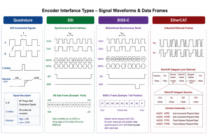 Encoder interface types and signal waveforms
3. How to Choose the Right Encoder for Humanoid Robots
Step 1 – Classify each joint by function.
Locomotion joints (hip, knee, ankle) must have absolute position to avoid homing moves that could destabilise the robot. Manipulation joints (shoulder, elbow, wrist, finger) can use incremental if homing is acceptable, but absolutes simplify emergency recovery. Head/torso joints often need higher resolution for vision‑guided tasks.
Step 2 – Calculate needed resolution.
For a rotary joint, convert your end‑effector positioning tolerance (e.g., 0.5 mm at 400 mm arm length) into angular resolution (~0.07°). Then divide by the gear reduction ratio (e.g., 50:1 harmonic drive) – a 12‑bit encoder (0.088° per count) gives an effective output resolution of 0.0018°, which is plenty for most tasks. For linear actuators, factor in leadscrew pitch or belt ratio.
Step 3 – Check control‑system compatibility and mechanical fit.
Verify your motion controller supports the chosen interface and can handle the total number of encoder channels. For 20+ DOF, distributed nodes over EtherCAT or CAN are far easier to wire than centralised analogue routing. Also confirm mounting style: hollow‑shaft encoders simplify integration but demand tight shaft tolerances; modular encoders with couplings add flexibility but introduce potential backlash. Miniature 16 mm OD encoders are available for fingers and wrists – use them.
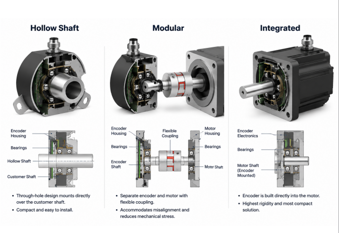 Encoder mechanical mounting types for robot joints
4. Performance Comparison Table
Table 1: Encoder Technology Comparison for Humanoid Robot Applications
| Technology | Resolution Range | Absolute/Incremental | Typical Accuracy | Shock Rating | Power Consumption | Relative Cost | Best Application |
|---|---|---|---|---|---|---|---|
| Optical Incremental | 100‑10,000 PPR | Incremental | ±0.1° to ±0.5° | 50G | 50‑150mA @5V | Low | Non‑critical joints, research |
| Optical Absolute (Single‑turn) | 12‑14 bit | Absolute | ±0.05° to ±0.2° | 50‑100G | 80‑200mA @5V | Medium | Most humanoid joints |
| Optical Absolute (Multi‑turn) | 12+12 bit turns | Absolute | ±0.1° to ±0.3° | 50‑100G | 100‑250mA @5V | High | Linear actuators, continuous rotation |
| Magnetic Absolute | 10‑14 bit | Absolute | ±0.2° to ±0.5° | 100‑200G | 20‑80mA @5V | Low‑Med | High‑shock, outdoor applications |
| Capacitive Absolute | 12‑17 bit | Absolute | ±0.05° to ±0.15° | 100G | 40‑100mA @5V | Med‑High | Precision manipulation, R&D |
| Resolver‑based | 12‑16 bit (after R/D) | Absolute | ±0.1° to ±0.3° | 200G+ | 200‑500mA @5‑15V | Medium | Harsh environments, high‑reliability |
Table 2: Interface Selection Based on Control Loop Requirements
| Interface Type | Max Update Rate | Typical Latency | Wiring Complexity | Multi‑drop | Best Use Case |
|---|---|---|---|---|---|
| A/B/Z Quadrature | >100 kHz | <10 µs | High (6+ wires) | No | Low‑cost incremental sensing |
| SSI | 100 kHz‑2 MHz | 5‑50 µs | Medium (4‑6 wires) | No | Real‑time joint control |
| BiSS‑C | Up to 10 MHz | 2‑20 µs | Medium (4‑6 wires) | Limited | High‑performance loops |
| EnDat 2.2 | Up to 16 MHz | 2‑15 µs | Medium (4‑6 wires) | Yes | Precision applications |
| CANopen | 1‑10 kHz | 100 µs‑1 ms | Low (CAN bus) | Yes | Distributed control, many joints |
| EtherCAT | 1‑20 kHz | 50‑500 µs | Low (Ethernet) | Yes | Networked high‑DOF systems |
5. Design Considerations and Common Pitfalls
Electrical – power and signal integrity.
Use dedicated low‑noise 5 V regulators for encoders – sharing with motor drivers invites ripple >100 mV, which introduces jitter in optical units. Add ferrite beads and bypass caps (10 µF + 100 nF) at each encoder. For cable runs over 2 m, use twisted‑pair or shielded cables, and ground the shield only at the controller end to avoid ground loops.
Mechanical – alignment and vibration.
Shaft misalignment is the top failure mode in field robots. Keep angular error <0.5° and parallel offset <0.1 mm with rigid couplings. For through‑hole encoders, verify shaft tolerance matches the bore – too loose and it slips, too tight and it overloads the bearing. In ankle/foot joints, use compliant mounts or damping washers to filter out high‑frequency (>500 Hz) vibration that can degrade optical or magnetic sensors over time.
Software – wrap‑around, delay, and index glitches.
Single‑turn absolutes need external revolution counters for continuous rotation joints – implement them, and test zero‑crossing behaviour. Commutation delay: at 3000 RPM, 1 ms latency equals 18° of electrical error – add feedforward or phase‑lead compensation. For incremental encoders, debounce the index pulse and only accept it when A/B indicate forward motion; false index triggers during bidirectional movement will corrupt your position.
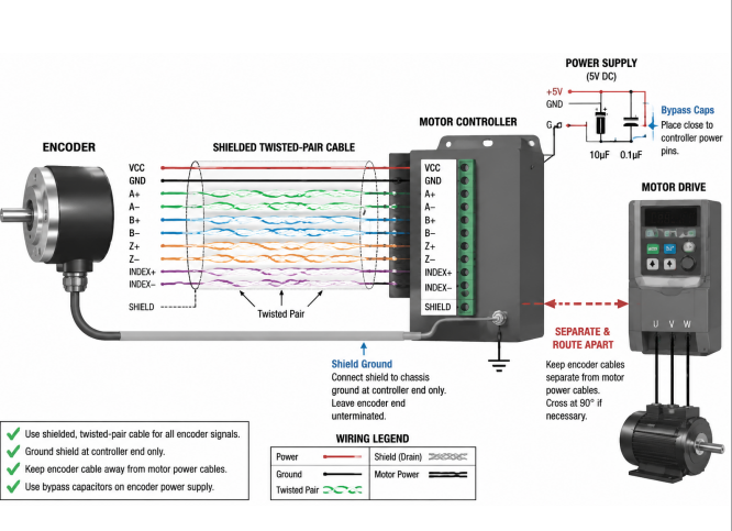 Proper encoder cable routing and grounding
6. Supply Chain and Sourcing Considerations
Lead times for standard catalog encoders (Renishaw, SICK, Heidenhain, US Digital, CUI) are typically 4‑8 weeks for <100 units; custom flanges or cables push that to 10‑16 weeks. Keep relationships with distributors (Digi‑Key, Mouser, Newark) who stock common variants for rapid prototyping. For production, design your joint controller with software‑configurable support for multiple interface types and resolutions – this lets you qualify a second source without a board spin.
Costs: magnetic absolutes run $15‑30 per joint, optical absolutes $40‑80, hardened precision units $150‑400. With 20+ joints, encoders can eat 5‑10% of total BOM. Consider a tiered approach – 13‑bit on lower limbs, 10‑bit on upper‑body non‑load‑bearing joints – to cut costs by ~30% without sacrificing functional performance. Always do incoming inspection: test idle current, handshake, and position stability over 360°. For volumes >50/month, build an automated test fixture to verify accuracy across temperature.
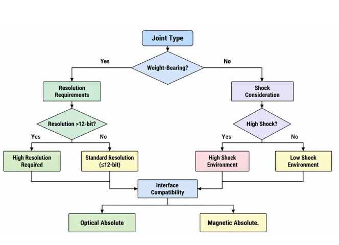 Encoder selection decision flowchart for humanoid robots
7. FAQ
What’s the real difference between absolute and incremental encoders for humanoids?
Absolute encoders give you valid position immediately after power‑up – no homing move, which is critical for load‑bearing joints where any unintended motion could topple the robot. Incremental encoders need a reference run, but they are cheaper and simpler; they work fine for upper‑body axes where homing is safe and routine.
How do I pick the right resolution for a given joint?
Start from your end‑effector accuracy requirement (e.g., 0.5 mm at 400 mm reach) → convert to angular resolution (~0.07°). Then divide by the gear reduction if the encoder is on the motor side. Multiply by a safety factor of 2‑3 to account for backlash and control quantisation – that gives your minimum bits/PPR.
Can I use magnetic encoders instead of optical ones?
Yes – magnetic types handle shock (100‑200G) and dirt better, making them ideal for outdoor or high‑impact joints. The trade‑off is lower resolution (10‑12 bit vs 12‑14 bit) and slightly poorer accuracy. Use magnetics for ankles/knees if shock is your main worry; stick with optical for precision manipulation (wrists, fingers).
Which interface works best for real‑time balance control?
For control loops at 1‑5 kHz, SSI or BiSS‑C give the lowest deterministic latency (5‑50 µs). CANopen and EtherCAT are convenient for many joints but add 250 µs‑1 ms – acceptable if your controller compensates. Avoid raw A/B/Z quadrature for critical loops because it’s prone to EMI glitches.
What should I do when an encoder communication error occurs?
Implement a watchdog that flags missing or corrupted data within 2‑3 control cycles. For non‑critical joints, hold the last valid position and log the fault. For locomotion joints, trigger an immediate controlled deceleration to a stable stance and activate a safe‑stop. Always store error logs – they are gold for post‑mortem analysis.
8. Conclusion
Choosing encoders for a humanoid isn’t about picking the “best” spec – it’s about matching the right technology, resolution, interface, and ruggedness to each joint’s role. For most platforms, 12‑13 bit optical absolutes with SSI/BiSS‑C offer the sweet spot for locomotion, while magnetic units shine where shock and dirt dominate. Networked interfaces (EtherCAT/CAN) win when you have 15+ joints and want to save wiring weight.
Good luck, and remember – the best encoder is the one that keeps working after the hundredth footfall.