




Sélection du CI du pilote LED : courant constant vs tension constante
Choisir la bonne topologie de pilote LED a un impact direct sur la durée de vie, l’efficacité et les coûts de conformité. Avec une efficacité des LED dépassant 200 lm/W en 2026 et des systèmes à faisceau matriciel automobile qui gagnent en adoption, la décision entre courant constant (CC) et tension constante (CV) affecte les frais de garantie, la conception thermique et les délais de certification. Ce guide couvre les critères de sélection, l’optimisation de l’efficacité, les méthodes de gradation et les compromis concrets basés sur des données de terrain issues des applications industrielles et des systèmes automobiles.
Table des matières
- [Comprendre les bases des pilotes LED] (#understanding-led-driver-fondamentaux)
- Courant constant vs tension constante : comparaison d’architecture
- [Quand utiliser chaque topologie] (#when-to-utiliser-chaque-topologie)
- [Implémentation de la gradation] (implémentation #dimming)
- [Gestion de l’efficacité et thermique] (gestion #efficiency-et-thermique)
- [Exigences automobiles et industrielles] (exigences #automotive et industrielles)
- FAQ
- Conclusion
Comprendre les bases des pilotes LED
Les LED sont des dispositifs à courant avec une tension directe (Vf) qui varie avec la température, la tolérance de fabrication et le vieillissement. Une LED blanche typique, évaluée à 350 mA, affiche une Vf de 2,8 V à 3,2 V par puce à une température de jonction de -40°C à +125°C. Sans régulation du courant, cette variation de tension de 14 % provoque des variations exponentielles du courant — pouvant dépasser 200 % du nominal — entraînant une fuite thermique en quelques heures.
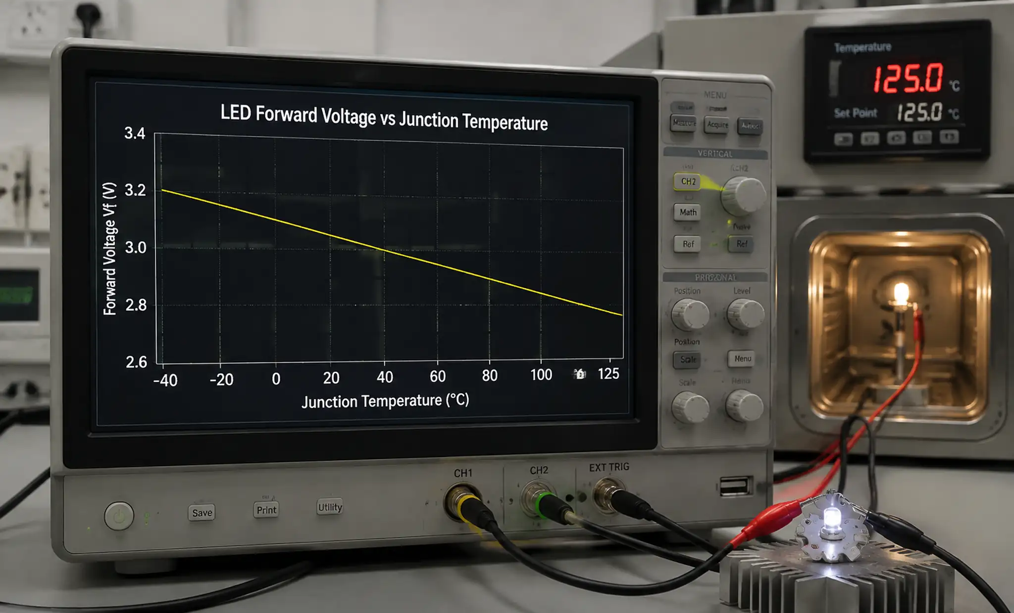 Variation de tension directe des LED sur la plage de températures montrant une dérive de la Vf de -40°C à 125°C
Les circuits intégrés de pilotage résolvent cela par courant constant (régulant le courant direct indépendamment de la variation de la Vf) ou une tension constante de sortie (tension stable avec limitation de courant externe). Le choix détermine le coût, l’efficacité et la complexité du système de la MOM. Les pilotes modernes atteignent une efficacité de 90 à 96 % grâce à la rectification synchrone et aux MOSFET intégrés.
Courant constant vs tension constante : comparaison d’architecture
| Paramètre | Courant constant (CC) | Tension constante (CV) |
|---|---|---|
| Méthode de régulation | Retour de courant via une résistance de détection ou un inducteur DCR | Retour de tension via le diviseur de résistance |
| Configuration LED | Cordes en série/parallèle directes, sans résistance de lest | Nécessite une limitation de courant externe par corde |
| Compensation Vf | Automatique — la sortie s’ajuste pour maintenir le courant | Aucun—la résistance absorbe la variation, gaspille de l’énergie |
| Efficacité | 90-96 % (pas de perte de lest) | 75-88 % (perte de 8 à 15 % en résistances) |
| Conception thermique | Chaleur concentrée dans le circuit intégré du haut-parleur | Distribué sur les résistances de ballast |
| Plage de Baisse | 0,01-100 % avec PWM ou analogique | Courbe non linéaire limitée dans les bas de gamme |
| Coût (100k vol) | 0,35 $ à 1,80 $ par circuit intégré | 0,20-0,60 $ IC + 0,10-0,25 $/chaîne |
| Meilleure utilisation | Haute puissance, automobile, critique couleur | Bandelettes LED, lampes de rénovation, charges réparties |
Les haut-le-cœurs CC mesurent le courant de sortie via une résistance de détection (10-50mΩ) et ajustent leur cycle de travail pour maintenir une régulation de ±3 %. Les haut-parleurs CV fournissent une tension fixe ; Les résistances externes limitent le courant mais gaspillent de l’énergie et créent des variations de luminosité. Pour trois LED 3,0V à 350 mA sur une alimentation CV 12 V : R = (12 V - 8,1 V) / 0,35A = 11Ω dissipant 1,3 W. À la puissance maximale de la Vf (9,9V), le courant descend à 190 mA — une réduction de 46 % provoque un assombrissement visible.
Quand utiliser chaque topologie
Choisissez Courant constant pour :
-
Éclairage de haute puissance (>10W) : Les feux lumineux commerciaux et l’éclairage public bénéficient de l’élimination des pertes de ballast. Un réseau de 100W à 90 % de CC gaspille 10W contre 18W avec une topologie CV — cette différence de 8W sur 50 000 heures représente des coûts énergétiques importants.
-
Éclairage automobile : Les conducteurs AEC-Q100 Grade 1 CC sont obligatoires pour les phares et les diamètres selon les FMVSS 108 et ECE R48. La plage transitoire 9-16V nécessite une régulation du courant pour maintenir une tolérance d’intensité lumineuse de ±5 %. En savoir plus sur les exigences en composants automobiles.
-
Applications critiques en couleur : la température de couleur des LED varie avec le courant. ± variation de 10 % du courant provoque un décalage de ±150K CCT dans les LED blanches de 3000 K — visiblement perceptible. La réglementation CC maintient <± dérive de 50K.
-
Séries de LED à décode : Alimenter 6+ LED en série (systèmes 48V DC) fait du CC le choix pratique. La CV nécessite une régulation précise de la tension et des bins LED assortis.
-
Large plage de gradation : La gradation PWM atteint un ratio de 10 000:1 (0,01-100 %) sans décalage de couleur, essentielle pour l’éclairage en studio et médical.
Choisissez Tension constante pour :
-
Éclairage à bande LED : les bandes architecturales 12V/24V avec segments découpables sur le terrain utilisent des alimentations CV. Chaque segment est équipé de résistances de limitation de courant intégrées, permettant une installation flexible sans recalculer les paramètres du pilote.
-
Lampes rétrofit : Les ampoules LED à base MR16, GU10 et Edison utilisent une entrée CV pour s’adapter à l’infrastructure existante, permettant un remplacement direct sans modification du luminaire.
-
Charges basses puissances distribuées : Pour les indicateurs inférieurs à 100 mA où l’efficacité est secondaire, la CV avec des résistances élimine la complexité du circuit intégré du pilote avec une pénalité de puissance minimale (0,05W par LED).
-
Charges LED mixtes : Les bus CV peuvent fournir simultanément différents bins ou couleurs Vf avec une limitation appropriée par chaîne. Le CC nécessite des cordes assorties.
Le principal inconvénient de la CV est la pénalité d’efficacité : une bande de 24V avec une guirlande LED 18V gaspille 25 % en résistances de ballast. Les circuits intégrés pilotes CC 2026 les plus importants incluent TI TPS92520 (2,5A, 95 % d’efficacité) et ON Semiconductor NCV78247 (certifié sécurité fonctionnelle de qualité automobile). Explorez nos catégories de produits pour obtenir des options d’approvisionnement.
Implémentation de la gradation
Les méthodes de gradation diffèrent considérablement entre les topologies, ce qui affecte la performance et l’efficacité du scintillement.
| Méthode de gradation | Implémentation CC | Implémentation CV | Profondeur | Efficacité |
|---|---|---|---|---|
| PWM (200Hz-25kHz) | Modulation de broche d’activation ou FET intégré | Chaîne de commutateurs FET externes | 0,01-100 % | Haut—transducteur éteint pendant la phase basse |
| Réduction analogique | Ajuster la tension de référence du courant | Non applicable sans contrôle de CC | 5-100 % | Légère perte à faible courant |
| 0-10V / DALI | Ensembles d’interface pour la tâche analogique ou PWM | Contrôle le FET externe ou le point de consigne | 1-100 % | Impact minimal |
| Coupe de phase (TRIAC) | Nécessite PFC + suppression du scintillement | Gros plafonnement de sortie, mauvaises performances | 5-100 % | Mauvaise fascie plantaire, facteur de crête élevé |
La gradation PWM commute le courant LED à >200Hz (>1 kHz pour les appareils photo). Les pilotes CC acceptent la PWM sur les broches d’activation ou intègrent les FIT contrôlés. Pendant les arrêts, le conducteur passe en mode basse consommation, maintenant l’efficacité à 1 % du cycle de service. Les systèmes CV nécessitent des MOSFET externes et le pilote fonctionne en continu, gaspillant de l’énergie en veille. Les condensateurs de sortie doivent se décharger complètement ou des effets fantômes surviennent à bas cycles de service.
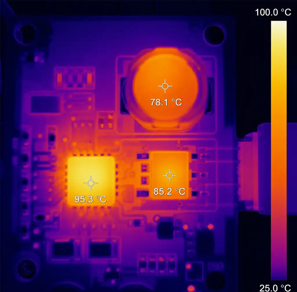 Image de la caméra thermique montrant la répartition de la chaleur sur les LED
CI de pilotage et inductance sous pleine charge La gradation analogique réduit la tension de référence du pilote CC, fonctionnant de façon fluide de 100 % à ~10 %. En dessous de 10 %, la ondulation de l’inductance devient significative, provoquant un scintillement. Les contrôleurs modernes (TI LM3409) maintiennent une ondulation de <5 % jusqu’à 50 mA, permettant un gradage de 5 % sur les LED de 1 A. Les topologies CV ne peuvent pas implémenter un gradage analogique sans compromettre leur simplicité architecturale.
Gradation matricielle automobile : Les systèmes ADB (Adaptive Driving Beam) utilisent des canaux CC indépendants par segment LED. TI TPS92642 fournit 12 CC avec rafraîchissement PWM à 1 kHz pour des feux de route sans éblouissements qui contournent le trafic entrant — impossible avec la topologie CV.
Efficacité et gestion thermique
L’efficacité des pilotes et la conception thermique impactent directement la durée de vie des LED. Chaque réduction de température de jonction de 10°C double la durée de vie de L70 selon la modélisation d’Arrhenius.
Efficacité topologique : Les convertisseurs buck atteignent leur efficacité maximale lorsque Vout < 0,8 × Vin. Une entrée 12V alimentant la chaîne LED 9V (3× 3,0V) atteint 94 % d’efficacité. La rectification synchrone remplace les diodes Schottky par des MOSFET à faible lait, économisant 0,5W à 1A de sortie — réduisant la température de la puce de 8°C dans les boîtiers MSOP-8. Le choix de l’inductance est important : Utiliser DCR <50mΩ et courant de saturation >1,3× Iout (max). Les noyaux en poudre moulés offrent une saturation douce pour les scénarios de décharge automobile où le courant peut monter de 2 ×. Un mauvais choix d’inductance provoque des baisses d’efficacité et des problèmes d’EMI.
Technologie GaN en 2026 : l’intégration du FET au nitrure de gallium (Power Integrations LinkSwitch-TN2) offre une efficacité de 96 % avec une réduction de taille de 50 % par rapport au silicium. La récupération inverse quasi nulle de GaN permet de commuter >1 MHz, réduisant ainsi le magnétisme.
Couplage thermique CC : Les pilotes CC montés sur le même dissipateur thermique que les LED contribuent à la charge thermique. Un réseau de 10W avec un driver efficace à 90 % dissipe 1,1W ; à 88 % d’efficacité, la perte monte à 1,4W. Avec un dissipateur thermique de 15°C/W, cette différence de 0,3 W augmente la température de jonction LED de 4,5°C, réduisant la durée de vie de L70 de 54 000 à 42 000 heures.
Chaleur des résistances CV : Les résistances de ballast diffusent la chaleur à travers les circuits imprimés. Une bande de 24 V avec six segments de 4 LED (6× résistances de 0,5 W = 3 W) crée des points chauds de 120°C dans les installations fermées, chauffant les LED proches et accélérant la dégradation — invisible dans les simulations.
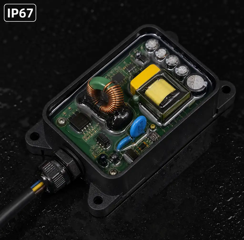
Exigences industrielles : Luminaires IP67 avec revêtement conforme, chauffage de siphon. Choisissez des haut-parleurs avec un arrêt thermique à 160°C et une limitation de courant de repliage — maintenir 70 % de puissance à 140°C est préférable à un arrêt brutal en éclairage de sécurité. Consultez nos services d’approvisionnement pour obtenir des composants thermo-classés.
Applications automobiles et industrielles
Les exigences réglementaires et les conditions environnementales difficiles influencent le choix de la topologie des pilotes dans les applications professionnelles.
Sécurité fonctionnelle automobile : La conformité ISO 26262 ASIL-B pour l’éclairage critique (phares, feux de frein) impose aux conducteurs CC des diagnostics — détection des LED ouvertes, protection contre les courts-circuits et signalement des surchauffes à l’ECU. ON Semiconductor NCV78247 intègre le bus SPI pour la télémétrie, rapportant en temps réel le courant par chaîne et la température de la puce pour une maintenance prédicte.
Conformité EMI : CISPR 25 Classe 5 des limites EMI effectuées et rayonnées nécessitent une disposition et un filtrage soigneux. La modulation de fréquence à spectre étalé (±10 % autour du FSW nominal) réduit l’EMI de crête de 8 à 12 dB sans pénalité d’efficacité. Placez les condensateurs d’entrée à moins de 5 mm de la broche VIN du pilote ; Utilisez des billes de ferrite en sortie vers les LED.
Protection contre les surtensions et les transitoires : Les applications industrielles selon la norme IEC 61000-4-5 nécessitent la surtension de 4kV ligne à ligne et de 6kV de ligne à sol. Les pilotes nécessitent des diodes TVS à l’entrée (série Littelfuse SMCJ, 600W de crête) et à la sortie (unidirectionnelle, Vbr > tension maximale de la chaîne LED). Le déchargement de charge automobile (ISO 7637-2 Impulsion 5a : 87V pour 400 ms) nécessite un arrêt de surtension en entrée et des composants homologués haute tension.
Vibrations et chocs mécaniques : IEC 60068-2-6 (10-500Hz, 5g) et les tests de choc (50g, 11ms semi-sinus) nécessitent un montage mécaniquement robuste sur inductance. Les inducteurs SMD blindés avec encapsulation époxy (série Coilcraft XAL) résistent aux vibrations ; Les inductances traversantes peuvent fissurer les soudures dans des environnements à forte vibration.
Pilote LED industriel avec revêtement conformif et montage d’inductance résistant aux vibrations pour applications minières
Cas réel : projecteur minier : Un projecteur LED de 200W pour l’exploitation souterraine fonctionne à 50°C ambiant avec 2g de vibrations continues et 95 % d’humidité. La conception utilise un pilote CC Meanwell HLG-240H-C1400B (1400mA, IP67, PFC actif) avec un revêtement conformal sur un renfortage d’inductance personnalisé. Après 18 mois (12 000 heures), le flux lumineux reste >98 % des marges initiales de conception thermique et mécanique validantes.
FAQ
Q : Puis-je remplacer un transducteur CV par un pilote CC dans un luminaire LED existant ?
Non, pas directement. Les luminaires CV possèdent des résistances de limitation de courant dimensionnées pour l’entrée CV ; la connexion du driver CC contourne les résistances et décharge les LED. Retirez les résistances et vérifiez que la tension totale de la chaîne LED se situe dans la plage de sortie du pilote CC. Les interfaces de gradation (0-10V, PWM) peuvent également être incompatibles.
Q : Pourquoi certaines bandes LED spécifient-elles à la fois un fonctionnement en 12V et 24V CV ?
La bande intègre des réseaux à détection de tension ou à double résistance qui s’adaptent à la tension d’entrée. Le fonctionnement en 24V réduit de moitié le courant pour la même puissance, réduisant la chute de tension du câble et permettant des passages plus longs — mais la dissipation des résistances augmente de (12V - Vf) à (24V - Vf), ce qui réduit l’efficacité.
Q : Qu’est-ce qui cause le scintillement des LED à faible cycle de travail PWM dans les systèmes CV ?
Le condensateur de sortie maintient la charge pendant l’arrêt du PWM, fournissant un courant résiduel aux LED. Augmentez la fréquence PWM à 1 kHz+ et ajoutez une résistance de purge sur toute la sortie (dimensionnée pour 5-10× courant de fuite LED en état éteint) pour décharger complètement le condensateur à chaque cycle.
Q : Les pilotes CC nécessitent-ils un binning LED spécifique pour plusieurs chaînes en parallèle ?
Oui. Les chaînes CC parallèles doivent utiliser le même binet Vf (tolérance ±0,1V) pour garantir un partage de courant dans ±10 %. Utilisez des drivers CC séparés par chaîne pour les bins mixtes, ou ajoutez de petites résistances d’équilibrage (0,5-1,0Ω) en série avec chaque chaîne.
Q : Puis-je obtenir un gradage de 0,1 % avec le contrôle du courant analogique ?
Théoriquement oui, mais le courant en ondulation et le temps de charge minimal de l’inductance limitent pratiquement l’atténuation à ~5 % avec l’analogique. Pour un gradage plus profond, utilisez PWM à 0,1 % de cycle de travail (1 ms allumé, 999 ms de réduction à 1 kHz) avec le contrôle activé par le driver CC.
Q : Quelle topologie de transducteur convient le mieux aux tubes LED rétrofit (remplacement du T8) ?
Des conducteurs isolés de CV ou CC avec détection interne de dérivation du ballast. Les tubes doivent détecter automatiquement les ballasts magnétiques/électroniques par opposition au courant alternatif direct et se reconfigurer en conséquence. Le type UL A (compatible ballast) utilise CV, le type B (fil direct) généralement CC avec PFC intégré.
Conclusion
Les haut-parleurs à courant constant offrent une efficacité supérieure, une qualité de gradation et une cohérence de flux lumineux supérieures pour l’éclairage général, l’automobile et les applications haute puissance où le coût total de possession justifie la prime de 0,40 $ à 1,20 $ en circuits intégrés. L’élimination des résistances de ballast permet de récupérer ce coût grâce à une consommation d’énergie réduite et à une durée de vie plus longue des LED — un système de 100W fonctionnant 8000 heures annuelles permet d’économiser 24 $ par an à 0,12 $/kWh en passant de 82 % (CV) à 92 % (CC).
Les pilotes à tension constante conservent leur utilité dans les applications de rénovation, les bandes architecturales nécessitant des segments découpables sur le terrain, et les systèmes distribués à faible consommation (<5W) où la simplicité l’emporte sur l’efficacité. L’essentiel est de reconnaître la pénalité d’efficacité de 8 à 15 % de CV et sa capacité de gradation limitée — acceptable pour l’éclairage d’accent, mais prohibitif pour les installations commerciales avec des milliers de luminaires. À mesure que l’efficacité des LED continue de s’améliorer vers les limites théoriques de 250 lm/W, l’efficacité des pilotes devient le principal mécanisme de perte, poussant l’industrie vers une adoption universelle des CC.
Pour les applications nécessitant à la fois flexibilité et efficacité, envisagez des approches hybrides : distribution primaire CV vers des zones avec régulation locale du CC par séance, ou pilotes CC intelligents avec capacité de sortie parallèle et équilibrage actif du courant. Un choix approprié de la topologie lors de la phase de conception évite des reconceptions coûteuses lors des essais réglementaires et du déploiement sur le terrain.